Architecture
5 minute read
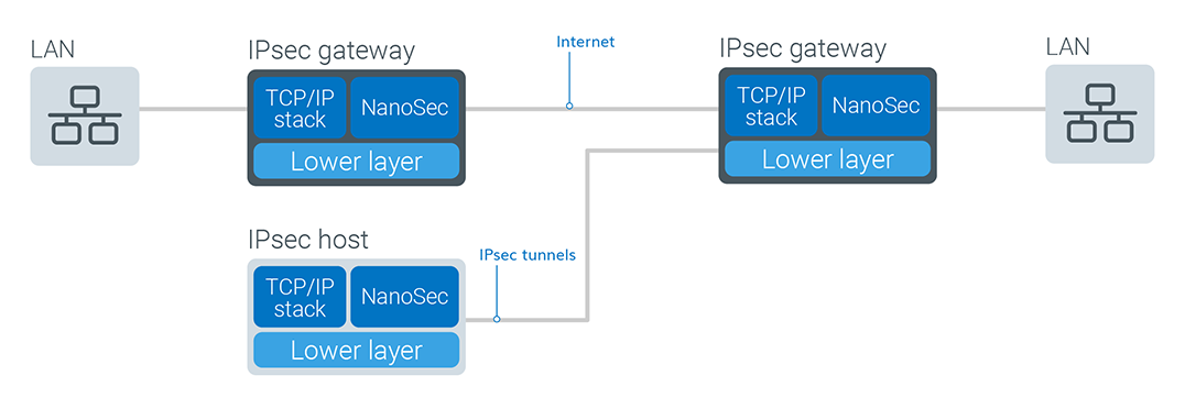
NanoSec uses encryption technology to provide data confidentiality, integrity, and authenticity between participating peers in a private network. The NanoSec components, IPsec, and IKE, are designed and optimized to operate together; however, NanoSec IPsec can be used with manual keying instead of using NanoSec IKE.
High-level network diagram
Authentication protocol support
NanoSec supports the following IPsec authentication protocols:
- Authentication Header (AH)–Allows authentication of the sender of data.
Note
AH mode is incompatible with Network Address Translation (NAT) because NAT changes the source IP address, which modifies the AH header, causing the peer to reject the packets. - Encapsulating Security Payload (ESP)–Supports both sender authentication and data encryption.
Unlike SSL and SSH, which provide services at TCP/IP Layer 4 (the application layer) and secure two applications, IPsec works at Layer 3 (the transport layer), providing stateless security (data confidentiality, data integrity, data source authentication, protection against traffic analysis, and anti-replay protection) for everything in the network.
Tunnel and transport encryption modes
NanoSec supports both tunnel and transport modes.
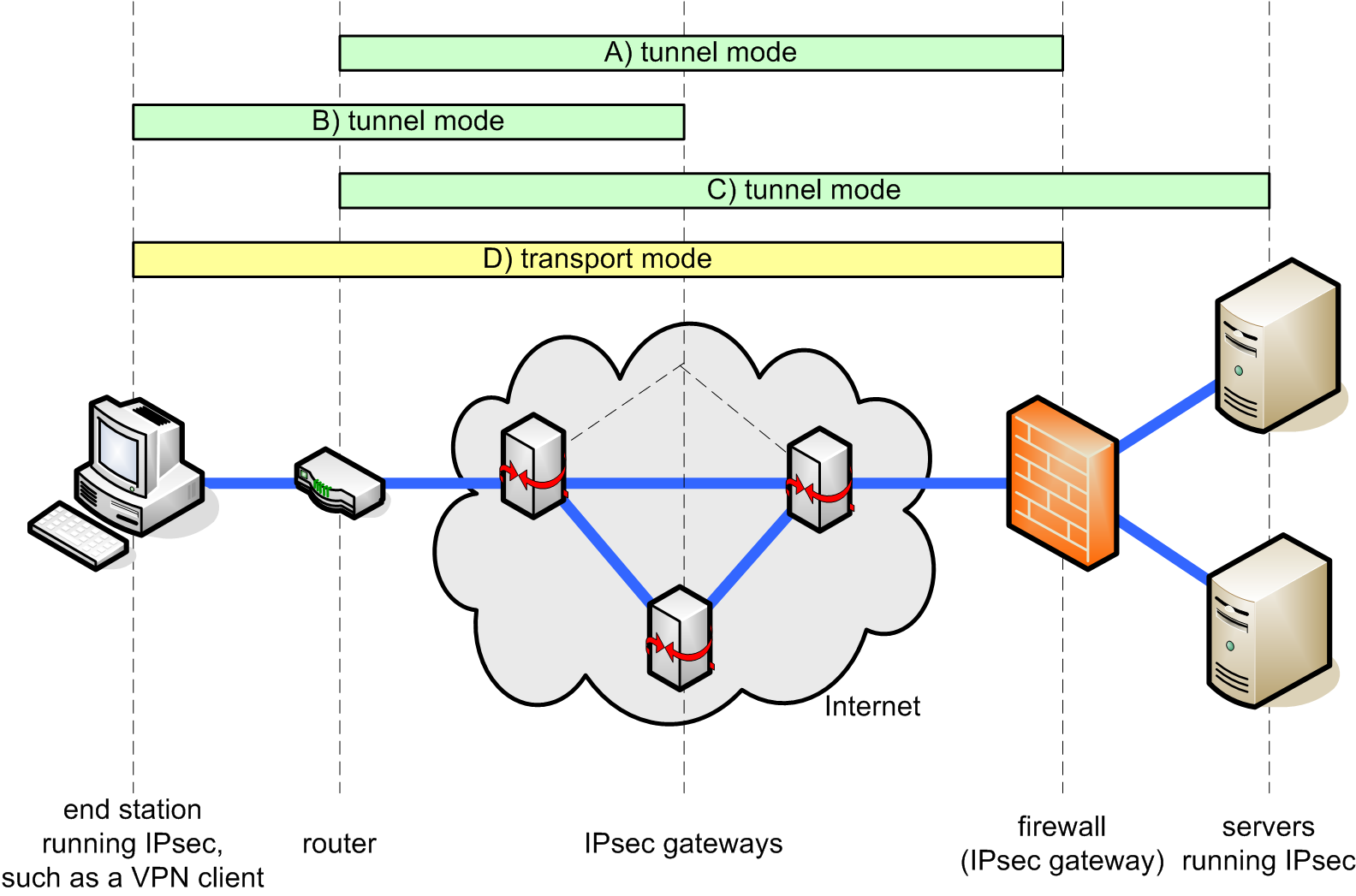
IPsec tunnel and transport modes
Tunnel mode
Tunnel mode provides protection to private network traffic between IPsec-enabled machines or devices acting as public gateways. To use tunnel mode, be sure to specify the tunnel IP address in the security policy. Add a line to the configuration, similar to the following:
{...} ipsec {tladdr 192.168.1.1 traddr 192.168.2.1}
Note: For more information, see tladdr, and traddr.
Transport mode
Transport mode is the default operation and provides end-to-end security for a two-machine peer-to-peer connection. The peer machines can be end-stations or gateways that are being treated as hosts. For example, transport mode is frequently used to encrypt a telnet session between a workstation and router, where the router is the actual destination.
- Example A shows the most common use for tunnel mode: encrypting traffic between secure IPsec gateways.
- Tunnel mode is also used to connect end stations running IPsec software (such as NanoSec or a VPN client) to an IPsec gateway, as shown in example B.
- In example C, tunnel mode is used to set up an IPsec tunnel between a router and a server running IPsec software.
- Example D illustrates the primary reason to use transport mode: to set up an encrypted Telnet session between an end station running IPsec and a remote end station or gateway (that is being treated as a host), for configuration and control purposes.
Best practice is to use transport mode for end-to-end sessions and tunnel mode for everything else.
MOBIKE
TrustCore SDK NanoSec supports MOBIKE, a mobility and multihoming extension to Internet Key Exchange (IKEv2).
As described in RFC 4555, “IKEv2 is used for mutual authentication, as well as establishing and maintaining IPsec Security Associations (SAs).” As originally designed, it was not possible to change the IP addresses that were used when the IKE SAs were established, thereby creating problems when an IP address must change due to mobility or multihoming.
Therefore, RFC 4555—IKEv2 Mobility and Multihoming Protocol (MOBIKE)—was developed to provide a mechanism for updating the IP addresses of existing IKE and IPsec SAs as needed. Typical MOBIKE scenarios include:
- Enabling a remote access VPN user to move from one address to another without re-establishing all security associations with the VPN gateway.
Such mobility can be “(mostly) invisible to applications and their connections using the VPN” because MOBIKE updates only the outer (tunnel header) addresses of IPsec SAs, leaving the addresses and other traffic selectors used inside the tunnel unchanged. - Seamlessly switching among any number of host interfaces; for example, a VPN gateway may have several network interfaces, which could be connected to different networks or ISPs, a mix of IPv4 and IPv6 addresses, or addresses that change over time.
MOBIKE operating restrictions
It is important to note that MOBIKE operation must comply with the following restrictions:
- Per RFC 4555, MOBIKE support is available only for IKEv2, not IKEv1.
- Both parties must support MOBIKE, which is confirmed during initial negotiation.
- Because there is no “rendez-vous” mechanism that allows simultaneous movement of both parties or discovery of the addresses when the IKE_SA is first established, MOBIKE is generally applicable when the address of at least one endpoint is relatively stable.
- Although MOBIKE allows both endpoints to be multihomed, only one pair of addresses is used for an SA at any time. Therefore, applications such as load balancing are not addressed by MOBIKE (RFC 4555).
- Although Network Address Translators (NATs) can be used, MOBIKE assumes that if NATs are present, the initiator is the party behind the NAT. The case where the responder’s address changes is not fully supported.
For additional explanation, refer to RFC 4555.
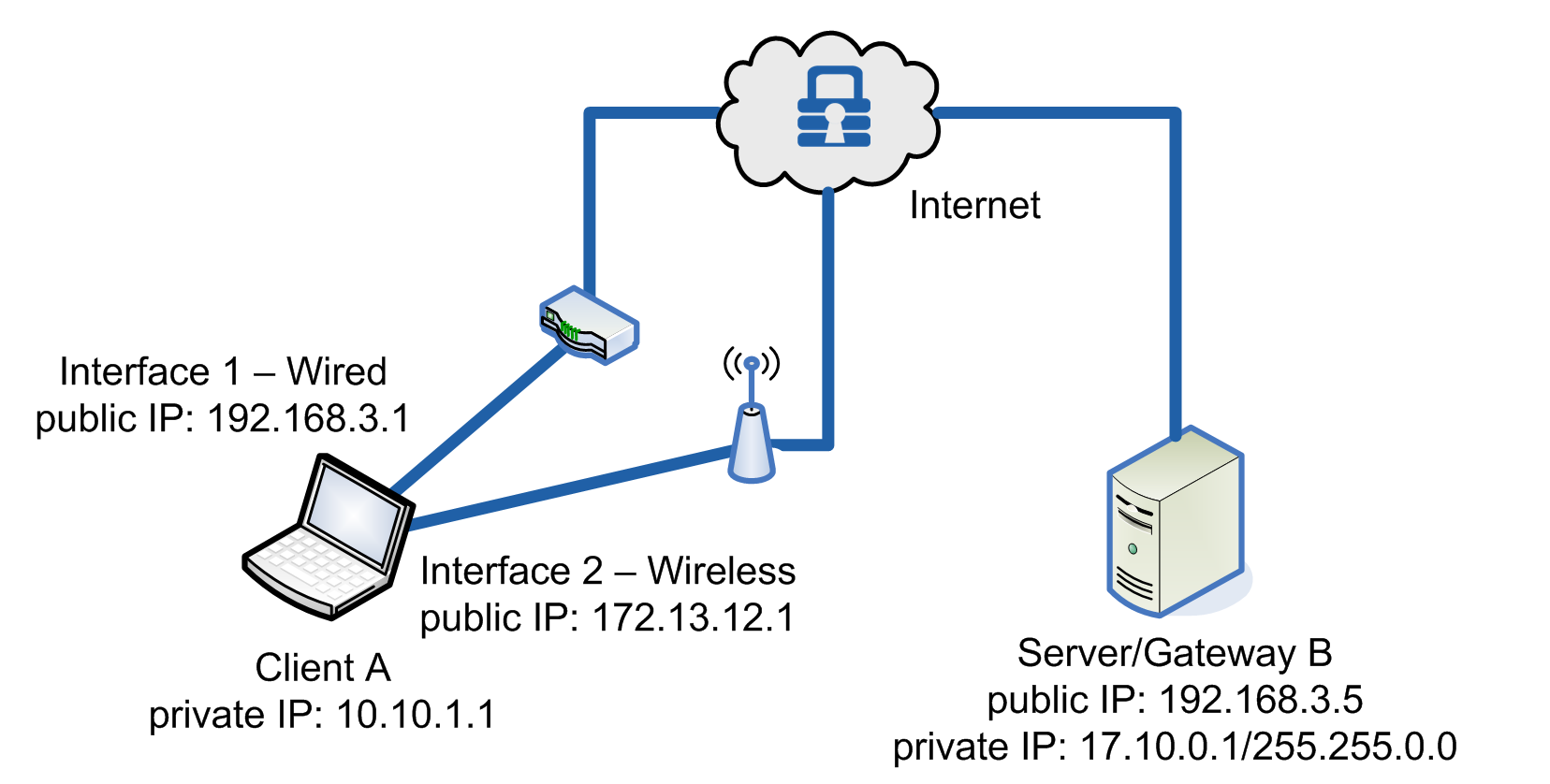
MOBIKE was developed to address situations where IP addresses change, such as:
- Roaming Devices: Smartphones and wireless-connected laptops are typical applications.
- Changing Interfaces: Changes from wired to wireless interfaces are typical applications.
For detailed examples of how to configure the NanoSec security policies for MOBIKE, see MOBIKE.
Roaming Devices
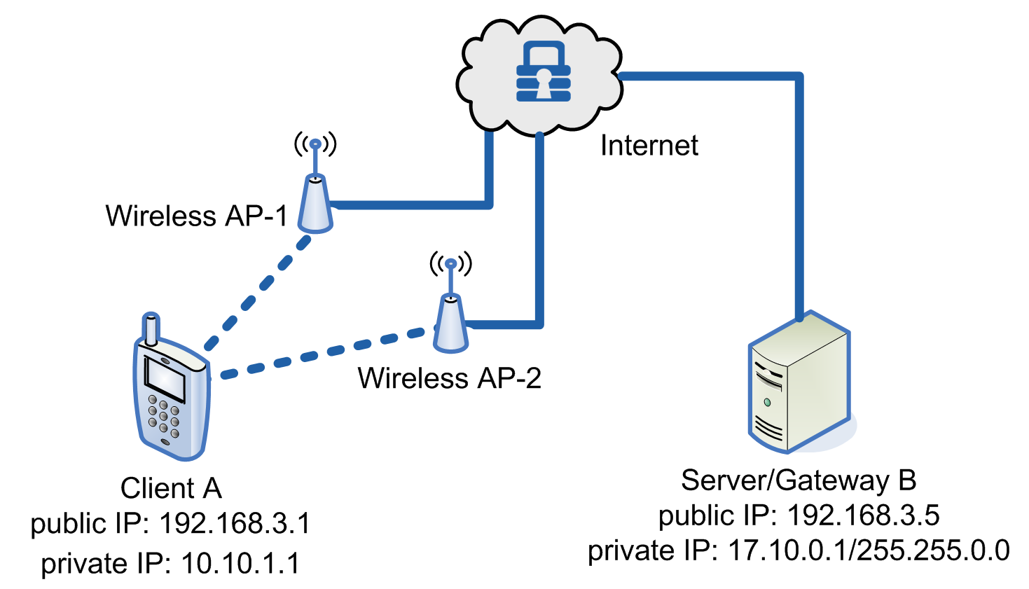
Below shows how MOBIKE is used when a device’s IP changes due to roaming.
Example of MOBIKE with changing public IPs due to roaming
Changing Interfaces
Below shows how MOBIKE is used when a device’s IP changes due to roaming.
Example of using MOBIKE to switch between a laptop’s two interfaces
Process Flowchart
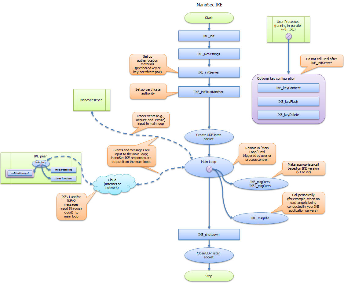
Below shows the typical NanoSec IKE process flow.
NanoSec IKE process flow
